Force Resistive Sensor Construction
Measurement and Instrumentation Class (2.671)
Resistive Sensors with the Vernier Data Logging Environment
The Vernier data logging systems are user-friendly environments for new experimentalists to quickly connect and log data from multiple streams. While Vernier has a wide library of sensors, it is not exhaustive. Some projects require an external sensor not in the Vernier library but available elsewhere. For this reason, Vernier sells cables for connecting with such sensors. On the left is an example of a force pad connected to the vernier cable, commonly used in running foot impact experiments.
As a teaching assistant, my role was to assemble (and repair) the sensors and show students how to use them, including calibration. I observed friction points that students encountered with these sensors. In response to these observations, I added AutoID and system power to all existing sensors and updated the assembly instructions to create a more streamlined and less obtrusive cable connection.
World of Resistive Sensors
The vernier cables may be connected to multiple types of resistive sensors. Below are a selection of resistive sensors I have assembled as part of my teaching assistant duties. The Vernier data logging environment registers these sensors as having a voltage output. Therefore, these sensors’ voltage range must be mapped to the range of the true variable of interest, usually via a separate calibration step.
Force/Pressure Pad
Force Pad - typically used to measure ground impact force while running.
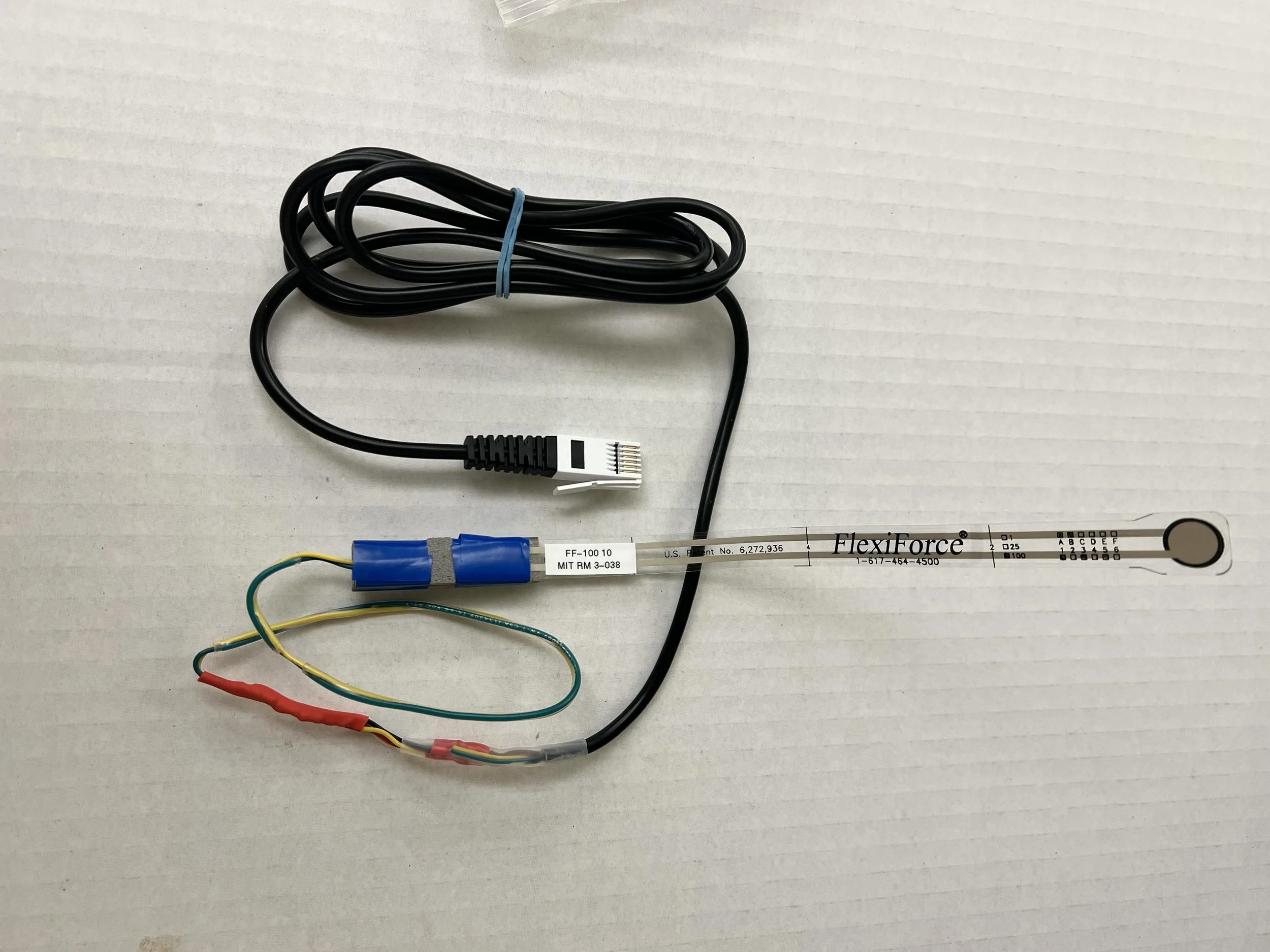
Flexi-force Sensor
Flexi-force Sensor - comes in range of sensitivities (1 lb, 10 lbs, 100 lbs). It has a smaller contact area and longer more flexible lead than the force pad. These features reduce measurement variation and in some applications, also makes the sensor less obtrusive for test subject. The 1-lb version is also used for applications where one wants to sense touch rather than measure force.
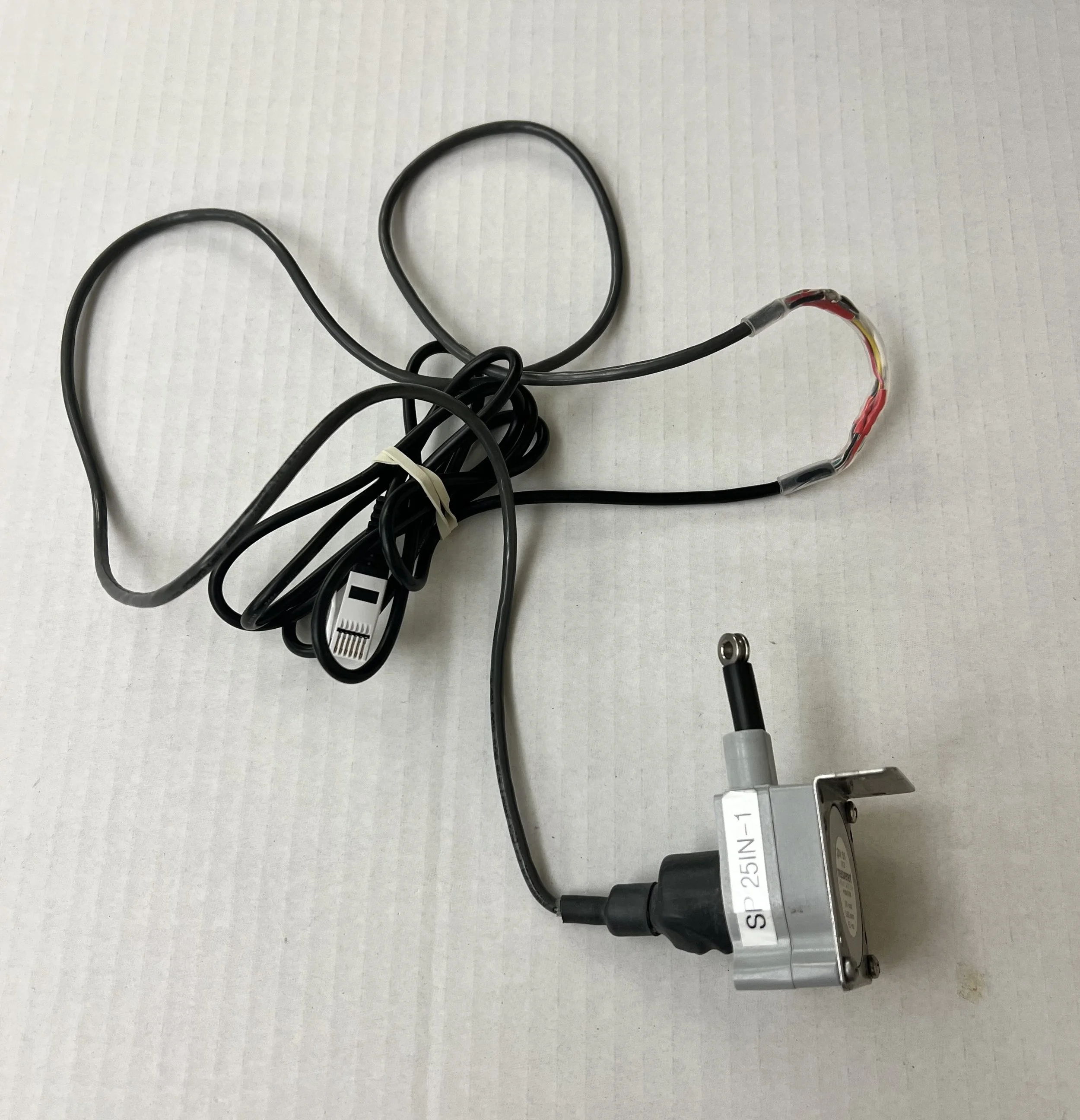
String Potentiometers
String Potentiometer: useful for measuring position and velocity. It comes in a variety of position ranges. The choice comes down to the desired range and resolution. Since the position range maps to the voltage range, an increased position range means reduced position sensitivity.
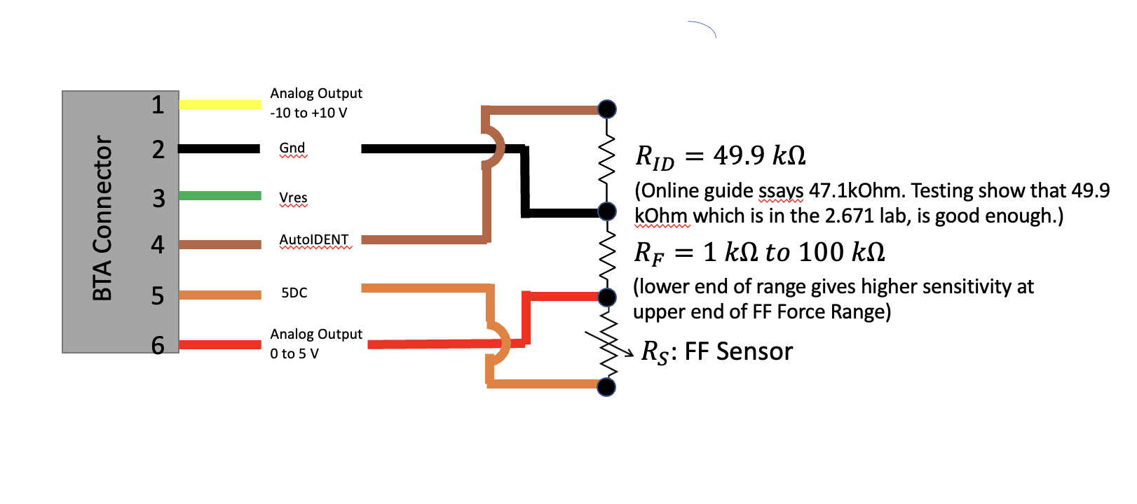
Schematic I made while designing the circuit for AutoID and system power. Pin 5 of the vernier cable provides a 5V output that is used as the reference voltage in lieu of the battery voltage. Vernier software reads the voltage on the AutoID (pin 4) to determine the sensor type. While the official documentation recommended a 47.1 kOhm resistor for the AutoID node, my own tests showed that the resistor needed to be even higher. I settled on 49.9 kOhm as it fell within the ‘good enough’ range and was on hand in bulk.
AutoID and System Power Integration - Reduce User Friction
Two key features of the assembly are AutoID and system power, which I integrated into all existing resistive sensors in the class library. Both features simplified the sensors' usage.
System Power: Switching to system power from battery power reduced data drift as the sensor output depended on the source voltage. When the battery decreased with use, so did the output voltage, leading to data drift.
AutoID: AutoID turns the sensors into ‘plug-and-play’. Otherwise, one needed to tell the data logging program to look for the sensor every time it was plugged in. My observations were that these extra steps added considerable friction to the user experience, especially with new users and during troubleshooting.
Construction Instructions
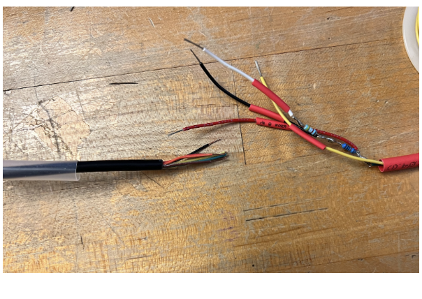
The assembly instructions for constructing the circuit to use AutoID and system power were documented for future persons to use. One of my design goals for the assembly was making the circuit streamlined and relatively indistinguishable from the surrounding cable. Any bulk increased the likelihood that the wire would catch during usage and pull the cable out of its socket. Therefore, the instructions include tips on when to add heat shrink to separate nodes, and approximately how long to cut wires and connections. Below shows the cable wiring in progress (left) and finished (right).
Wires prior to soldering, showing heat shrink separating circuit nodes. On the left are the BTA connector wires (pins 1 to 6). On the right are the sensor connections and resistors making up the rest of the circuit.
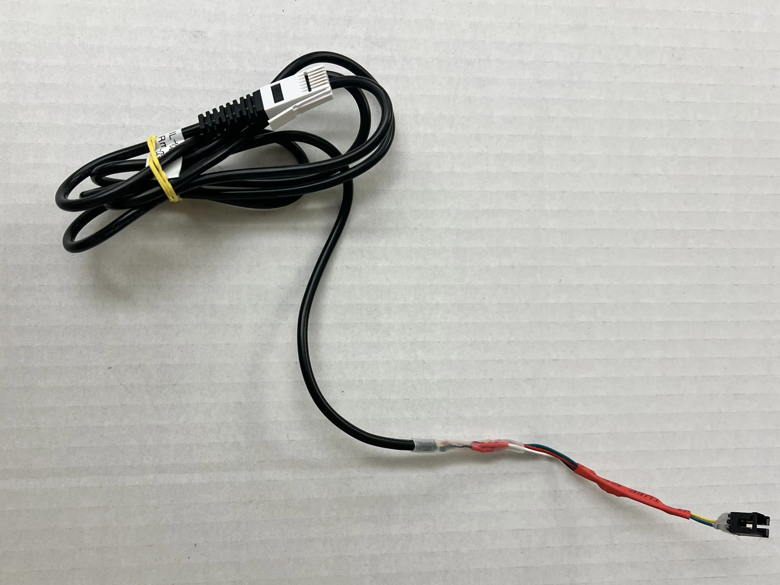
Complete cable. On the far right end is the connector to the force resistive sensor pad. Prior to the this connector, more heat shrink covers the streamlined circuit components.

